Title: NeXT RGB Board
Post by: gtnicol on December 13, 2013, 09:20:29 PM
Post by: gtnicol on December 13, 2013, 09:20:29 PM
I believe this is a board NeXT used for connecting to projectors (I originally thought they were Extron boards, but apparently not). I've never actually put one of these in a cube, but I am thinking of trying it out this weekend. I can't think of what that cable would be connected to. Any ideas?

Title: NeXT RGB Board
Post by: barcher174 on December 13, 2013, 11:59:09 PM
Post by: barcher174 on December 13, 2013, 11:59:09 PM
I'm curious, what are those screws under the cable?
Title: NeXT RGB Board
Post by: cubist on December 14, 2013, 12:46:09 AM
Post by: cubist on December 14, 2013, 12:46:09 AM
Quote from: "barcher174"I'm curious, what are those screws under the cable?Heat sink for 78xx/79xx series voltage regulators. The heat sink being a big piece of copper plane in these cases (most likely).
Title: NeXT RGB Board
Post by: pentium on December 14, 2013, 02:18:17 AM
Post by: pentium on December 14, 2013, 02:18:17 AM
Ooh, I know that board *scans through Fall '90 catalogue*
It does actually list it as the Extron board from Extron Electronics (and if you want more info, you called Extron's Santa-Fe Springs office)
Aside frrm half a page of text and a photo I have no additional details however it seems Extron did make another adapter which took your monitor connector and broke it to a monochrome composite output using RGB so I suspect the four BNC jacks are RGB and composite sync however this won't give you color.
It does actually list it as the Extron board from Extron Electronics (and if you want more info, you called Extron's Santa-Fe Springs office)
QuoteThe board accepts the 63khz horizontal, 68.3hz vertical high-resolution scan rate data directly from the internal vidoe data bus. Data timing are manipulated in memory to generate an interlaced video output at approximately 31khz horizontal and 34hz vertical. The result it the same apparent video resolution at a lower scan rate that's compatible with many multican type monitors and projectors.
Aside frrm half a page of text and a photo I have no additional details however it seems Extron did make another adapter which took your monitor connector and broke it to a monochrome composite output using RGB so I suspect the four BNC jacks are RGB and composite sync however this won't give you color.
Title: NeXT RGB Board
Post by: gtnicol on December 14, 2013, 08:01:50 AM
Post by: gtnicol on December 14, 2013, 08:01:50 AM
I thought it was an Extron too, but the logo on there says NeXT. The output appears to be RGB+S... I guess the theory of this is that you could have the board in a cube hooked up to a projector etc. while still being connected to either a soundbox and/or a display, and it would mirror the video on the display. It *seems* to be a pretty simple device, so it might be something people could replicate (be great if we could find the connectors for the bus... could make out own boards).
The screws are for a 7805C.
The screws are for a 7805C.
Quote from: "pentium"Ooh, I know that board *scans through Fall '90 catalogue*
It does actually list it as the Extron board from Extron Electronics (and if you want more info, you called Extron's Santa-Fe Springs office)QuoteThe board accepts the 63khz horizontal, 68.3hz vertical high-resolution scan rate data directly from the internal vidoe data bus. Data timing are manipulated in memory to generate an interlaced video output at approximately 31khz horizontal and 34hz vertical. The result it the same apparent video resolution at a lower scan rate that's compatible with many multican type monitors and projectors.
Aside frrm half a page of text and a photo I have no additional details however it seems Extron did make another adapter which took your monitor connector and broke it to a monochrome composite output using RGB so I suspect the four BNC jacks are RGB and composite sync however this won't give you color.
Title: NeXT RGB Board
Post by: gtnicol on December 14, 2013, 08:03:15 AM
Post by: gtnicol on December 14, 2013, 08:03:15 AM
Any thoughts on the cable? That one has me really curious.
Title: NeXT RGB Board
Post by: jroark on December 14, 2013, 11:27:15 AM
Post by: jroark on December 14, 2013, 11:27:15 AM
There is no NBIC, I wonder if all those 7x ICs are the NBIC? Does the cable just plug into the MB or maybe a ND?
Title: NeXT RGB Board
Post by: gtnicol on December 14, 2013, 11:57:04 AM
Post by: gtnicol on December 14, 2013, 11:57:04 AM
I think all the memory is used to buffer, and thereby change the scan rate. I initially thought that the cable might plug into the motherboard or dimension, but there's nowhere for it to connect to!
Title: NeXT RGB Board
Post by: pentium on December 14, 2013, 12:08:07 PM
Post by: pentium on December 14, 2013, 12:08:07 PM
QuoteI thought it was an Extron too, but the logo on there says NeXT.The photo I have has the NeXT logo on it too.
Edited: Oh, I know what the ribbon cable is for! Look in the lower right of an 040 board in the video section.

There's an unpopulated header with the correct number of pins and in reach of the tiny cable. It's an internal video header! :shock:
Edited: Oh god, my mind is now swirling with ideas like an 040 in the painted black case of an iMac G5.
Title: NeXT RGB Board
Post by: gtnicol on December 14, 2013, 12:44:55 PM
Post by: gtnicol on December 14, 2013, 12:44:55 PM
Now that's interesting. I think I have a motherboard with that header broken out, so yes, that makes sense.
Title: NeXT RGB Board
Post by: pentium on December 14, 2013, 01:16:08 PM
Post by: pentium on December 14, 2013, 01:16:08 PM
By off chance, is the header on the backside of your 040 board? There's no way the cable can reach the other side of the board.
Edited: Also, is there an extra component under the connector? There's a lone empty set of pads on the board I pictured.
Edited: Also, is there an extra component under the connector? There's a lone empty set of pads on the board I pictured.
Title: NeXT RGB Board
Post by: jroark on December 14, 2013, 03:02:15 PM
Post by: jroark on December 14, 2013, 03:02:15 PM
Cool, if it's just RGB/S a VGA expansion board could be possible.
I see a bunch of 74x ICs, 6x CA3054 DUAL OP-AMPs, and a couple AMD AM7201-25PC FIFOs
gtnicol, maybe a parts list and some closeups of the top and bottom?
Anyone good at tracing circuits?
I see a bunch of 74x ICs, 6x CA3054 DUAL OP-AMPs, and a couple AMD AM7201-25PC FIFOs
gtnicol, maybe a parts list and some closeups of the top and bottom?
Anyone good at tracing circuits?
Title: NeXT RGB Board
Post by: gtnicol on December 14, 2013, 04:38:59 PM
Post by: gtnicol on December 14, 2013, 04:38:59 PM
I'll have to dig up the board, but yes, from memory it had a gray connector on the back of the board.
I'll try and get some better photos... my scanner doesn't quite handle the size of the NeXT boards.
I'll try and get some better photos... my scanner doesn't quite handle the size of the NeXT boards.
Quote from: "pentium"By off chance, is the header on the backside of your 040 board? There's no way the cable can reach the other side of the board.
Edited: Also, is there an extra component under the connector? There's a lone empty set of pads on the board I pictured.
Title: NeXT RGB Board
Post by: gtnicol on December 14, 2013, 06:07:17 PM
Post by: gtnicol on December 14, 2013, 06:07:17 PM


Title: NeXT RGB Board
Post by: pentium on December 14, 2013, 07:26:21 PM
Post by: pentium on December 14, 2013, 07:26:21 PM
WOAH! The connector is on the 030 board too!
Yep, you got an extra Motorola chip. I can't make out the part number on it though. Might be important.
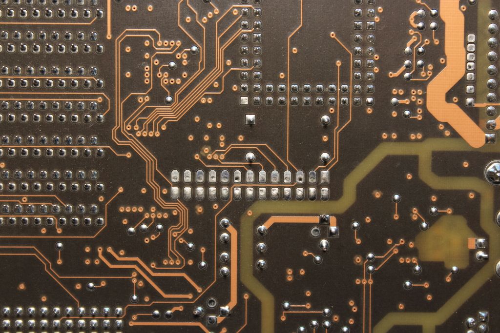
Edited: looking at my own 040 board it IS very important to that connector. At least 11 traces snake from the pads to the connector.
Let me take some high-res photos of this.
Yep, you got an extra Motorola chip. I can't make out the part number on it though. Might be important.
Edited: looking at my own 040 board it IS very important to that connector. At least 11 traces snake from the pads to the connector.
Let me take some high-res photos of this.
Title: NeXT RGB Board
Post by: gtnicol on December 14, 2013, 08:22:31 PM
Post by: gtnicol on December 14, 2013, 08:22:31 PM
I'll see if I can get some better pictures using my kids camera... 5MP vs. 8MP should make a difference...
Title: NeXT RGB Board
Post by: gtnicol on December 14, 2013, 08:40:05 PM
Post by: gtnicol on December 14, 2013, 08:40:05 PM
The extra chip is SC63594FN RMBY8849.
Title: NeXT RGB Board
Post by: pentium on December 14, 2013, 08:52:47 PM
Post by: pentium on December 14, 2013, 08:52:47 PM
Front and back.
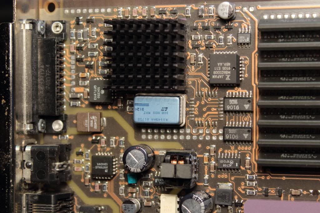
The SC63594FN from what I've found so far (I think) is a 10-bit series buffer/line driver with 20 ohm outputs.


The SC63594FN from what I've found so far (I think) is a 10-bit series buffer/line driver with 20 ohm outputs.
Title: NeXT RGB Board
Post by: gtnicol on December 15, 2013, 12:05:35 PM
Post by: gtnicol on December 15, 2013, 12:05:35 PM
If that's all it is, then we actually have a chance at producing a VGA board for the NeXT machines. From looking at the rest of the board, it's mostly just memory buffers and whatnot... possible to replace with some more modern approaches even.
Title: NeXT RGB Board
Post by: pergamon on December 15, 2013, 03:18:28 PM
Post by: pergamon on December 15, 2013, 03:18:28 PM
I completely forgot, but I've got one of these too: http://www.flickr.com/photos/mgrdcm/sets/72157638709188844/
Looks to be the same board. Same part number (534 REV AF). I don't have the cable though.
Looks to be the same board. Same part number (534 REV AF). I don't have the cable though.
Title: NeXT RGB Board
Post by: gtnicol on December 15, 2013, 05:21:41 PM
Post by: gtnicol on December 15, 2013, 05:21:41 PM
Do you have a modified motherboard? I only have the one...
Title: NeXT RGB Board
Post by: pergamon on December 15, 2013, 05:25:03 PM
Post by: pergamon on December 15, 2013, 05:25:03 PM
Quote from: "gtnicol"Do you have a modified motherboard? I only have the one...
Sadly, no, I don't believe I do. I'll have to double check - I got that board in a lot with a few other cubes and I may just not have noticed. But by now I don't know which ones were with it, so I'll have to check all of them...
Title: NeXT RGB Board
Post by: pentium on December 15, 2013, 10:52:41 PM
Post by: pentium on December 15, 2013, 10:52:41 PM
By the way, if we decide to make some sort of paddleboard that plugs into the socket instead of a complete board an a neighboring slot, those eight pads in the corner of the board supply +12 and -12v.
The seven pads immediately behind the monitor connector are all ground.
The seven pads immediately behind the monitor connector are all ground.
Title: NeXT RGB Board
Post by: NeXTnewbe on December 16, 2013, 07:44:00 AM
Post by: NeXTnewbe on December 16, 2013, 07:44:00 AM
Wow, Great find, where did you get this board from?