Title: Need help finding MLCC value for Non-ADB sound board.
Post by: SlateBlue on April 05, 2017, 02:25:22 PM
Post by: SlateBlue on April 05, 2017, 02:25:22 PM
Hi guys,
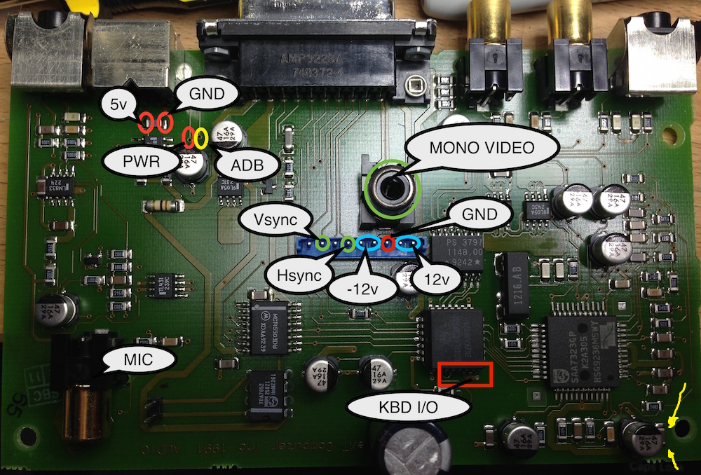
In the process of recapping my monitor's soundboard, I suspect I physically damaged on of the MLCC on one corner of the board. (See borrowed [barcher's?] image for MLCC location -yellow arrows.) By damage, it appears that one corner near the pad end of the cap has been slightly melted. I am unable to find a schematic, nor do I know how to find the value of the damaged MLCC. I was hoping some of you would be able to help.
The best I can tell, it looks like it is labeled "A5 5"? Again, it's very difficult to tell. I would appreciate if someone could chime in with the proper value so I can replace it. Thanks!

Title: Need help finding MLCC value for Non-ADB sound board.
Post by: SlateBlue on April 05, 2017, 06:28:53 PM
Post by: SlateBlue on April 05, 2017, 06:28:53 PM
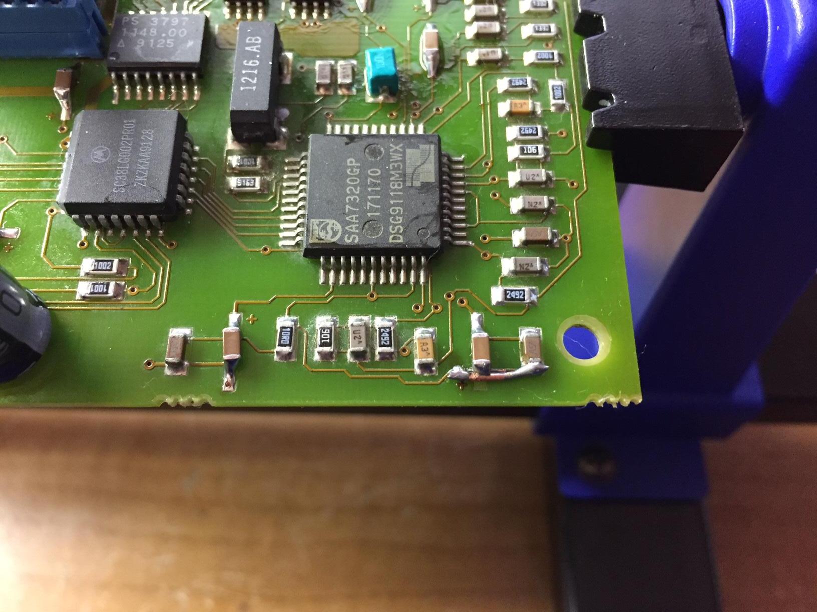
Upon further inspection, it appears the MLCC is labeled "A5A." The last "A" is superscript. Typing the number into Mouser's search yields a few results for 1000pF 50v MLCCs. Anyone care to speculate if I can get away with using a MLCC rated for 16v?
Photos of my actual soundboard should explain why this cap appears to be damaged. A pad lifted as I was prepping to solder the new 47uF MLCC to the left. My repair of the pad and trace isn't pretty, but continuity checks out.

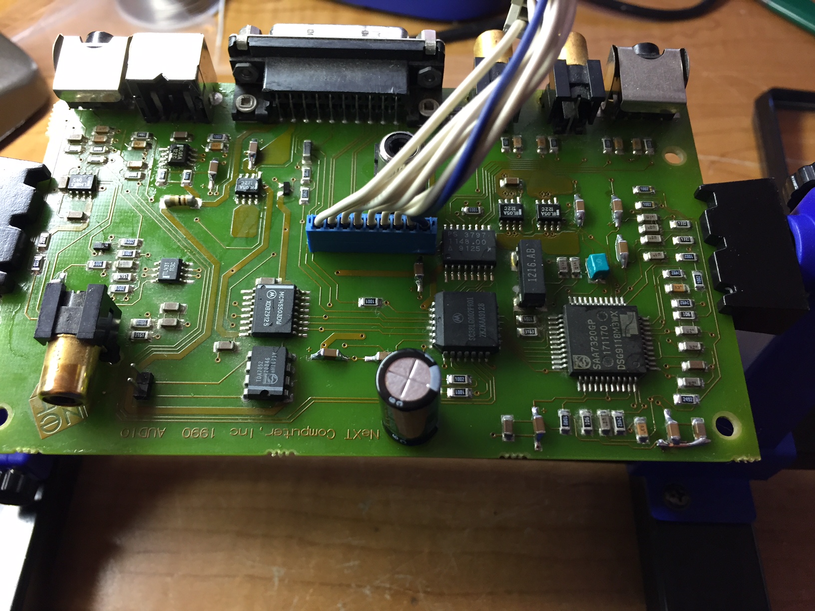
Photos of my actual soundboard should explain why this cap appears to be damaged. A pad lifted as I was prepping to solder the new 47uF MLCC to the left. My repair of the pad and trace isn't pretty, but continuity checks out.

Title: Need help finding MLCC value for Non-ADB sound board.
Post by: cubist on April 06, 2017, 01:09:52 AM
Post by: cubist on April 06, 2017, 01:09:52 AM
I don't have the schematics for these at hand but that's a standard power supply filtering idiom. Large electrolytic in parallel with a smaller film or ceramic capacitor. It will be identical to the capacitor on the left of that bottom row of components. A typical value would be 0.1uF or a bit lower. Your move to ceramics from aluminum electrolytics changes things and may make this part unnecessary. If you want a part anyway, you can solder it piggy-backed on the 47uF you put in.
I'd also verify that those really are 47uF of suitable voltage rating.
I'd also verify that those really are 47uF of suitable voltage rating.
Title: Need help finding MLCC value for Non-ADB sound board.
Post by: SlateBlue on April 08, 2017, 08:07:25 PM
Post by: SlateBlue on April 08, 2017, 08:07:25 PM
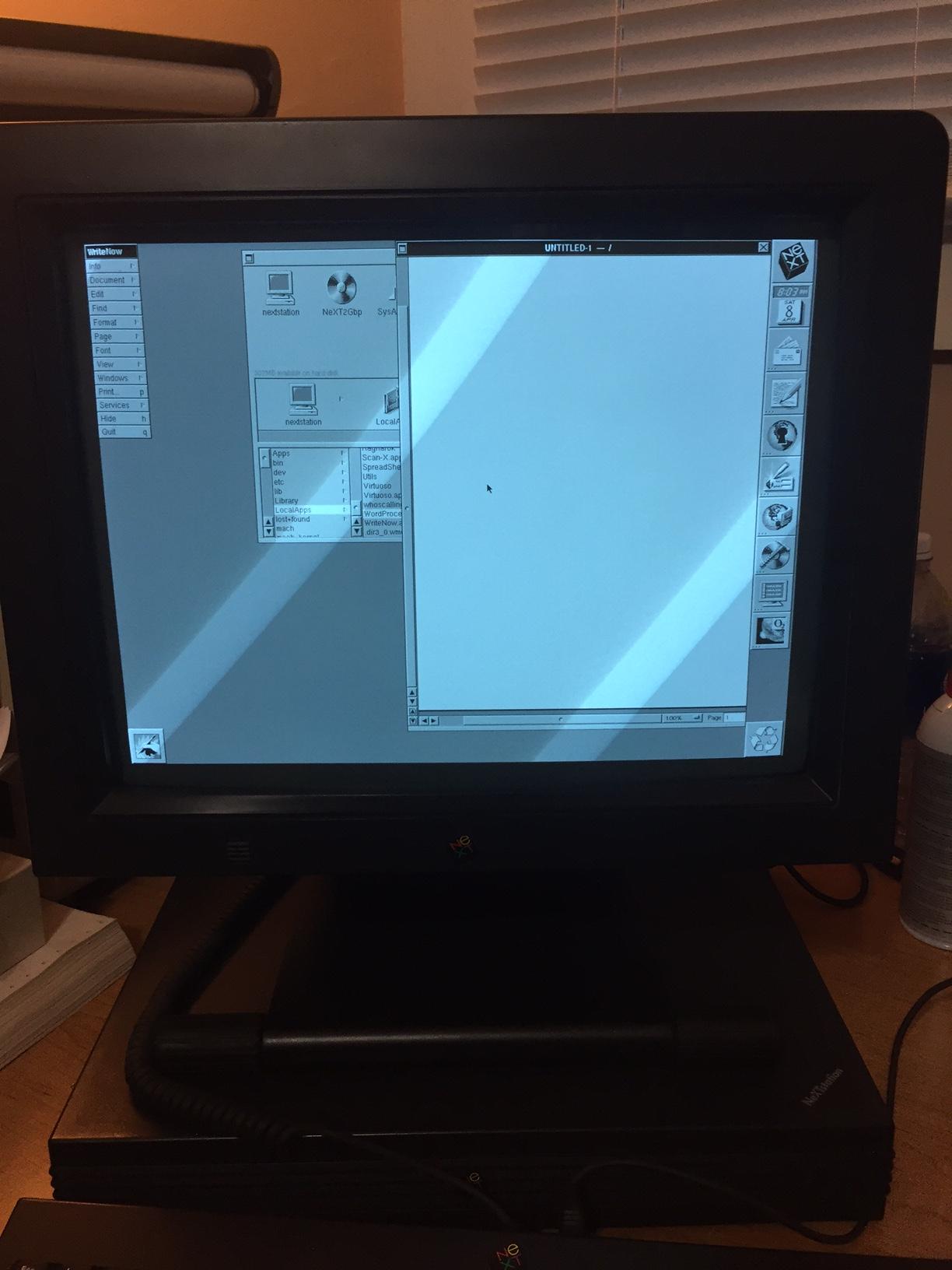
Thank you for the education. I wondered why those caps were soldered in parallel. I ended up using a 1000pF 16v cap (ordered before seeing your post) to replace the one I damaged. I finished recapping the analog board, and I'd like to report that the venture has been successful. My original reason for wanting to recap was due to "fluttering" along the screen edges that went away after 5 minutes of being powered on. The screen is noticeably more stable; I did adjust the white level to brighten the CRT a bit. Should be good for another few years...

Title: Need help finding MLCC value for Non-ADB sound board.
Post by: cubist on April 09, 2017, 04:11:51 PM
Post by: cubist on April 09, 2017, 04:11:51 PM
This topic made me look at the 7320 datasheets on the web and this confirms another problem: bad docs. What I found were scans of preliminary datasheets and I think they're incorrect (also inadequate lacking application notes). For example, pin 35 (MUTE_bar) isn't wired as I'd expect.
Need to get some scans of real documentation from the Philips and Moto books of the era and archive them here.
Need to get some scans of real documentation from the Philips and Moto books of the era and archive them here.
Title: Need help finding MLCC value for Non-ADB sound board.
Post by: gtnicol on April 18, 2017, 09:40:22 AM
Post by: gtnicol on April 18, 2017, 09:40:22 AM
I may have the design documents for the soundbox board. Let me see if I can dig them up.
Title: Need help finding MLCC value for Non-ADB sound board.
Post by: barcher174 on April 18, 2017, 07:45:38 PM
Post by: barcher174 on April 18, 2017, 07:45:38 PM
I would be -very- interested if you do.