Title: Turbo Color Slab Motherboard Repair and Recap
Post by: Nitro on April 30, 2024, 02:15:13 PM
Post by: Nitro on April 30, 2024, 02:15:13 PM
Back around 2006 or so I purchased a 25MHz cube motherboard and a Turbo Color slab motherboard from eBay. Unfortunately both motherboards were shipped in the same oversized box with only a thin plastic grocery bag as padding. Needless to say the two boards beat each other up during shipment. The cube motherboard required repair to one of the RAM slots, a new EPROM chip, soldering in a new VRAM chip, and a good recapping to get it up and running.
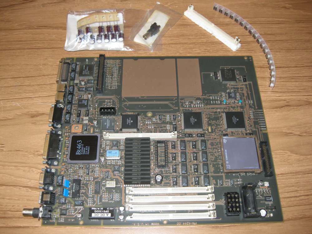
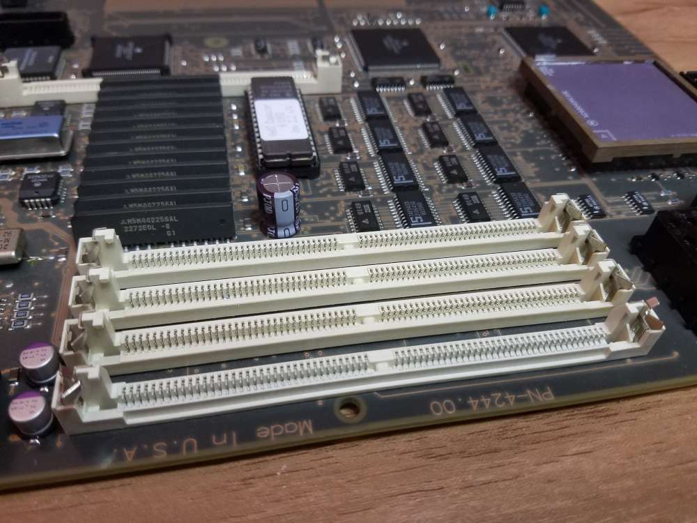
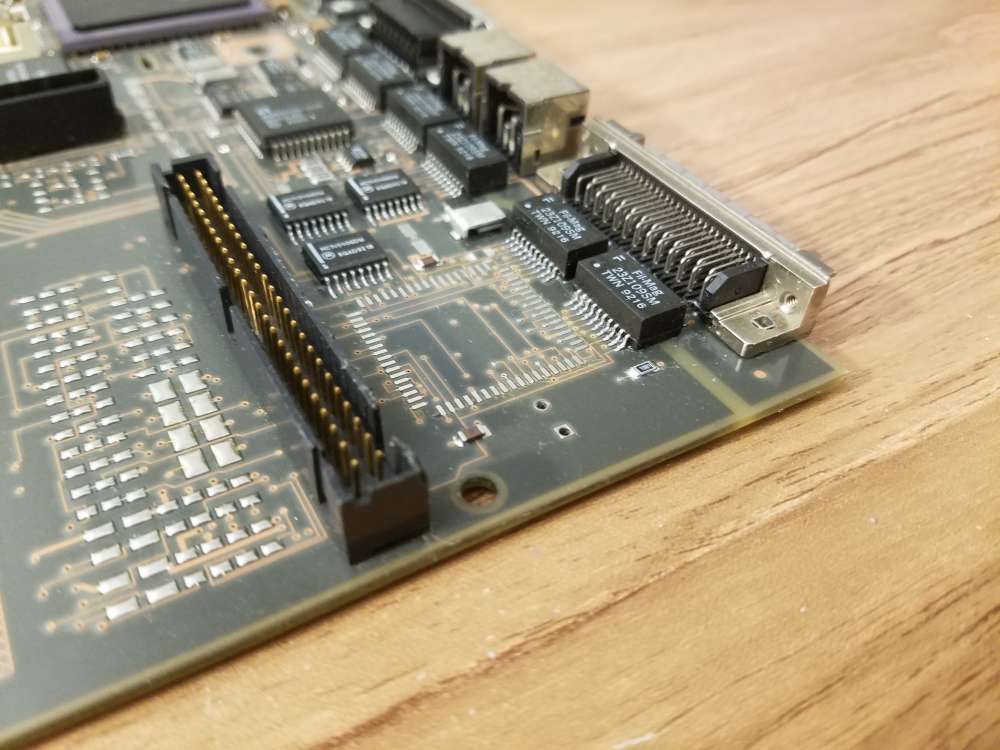
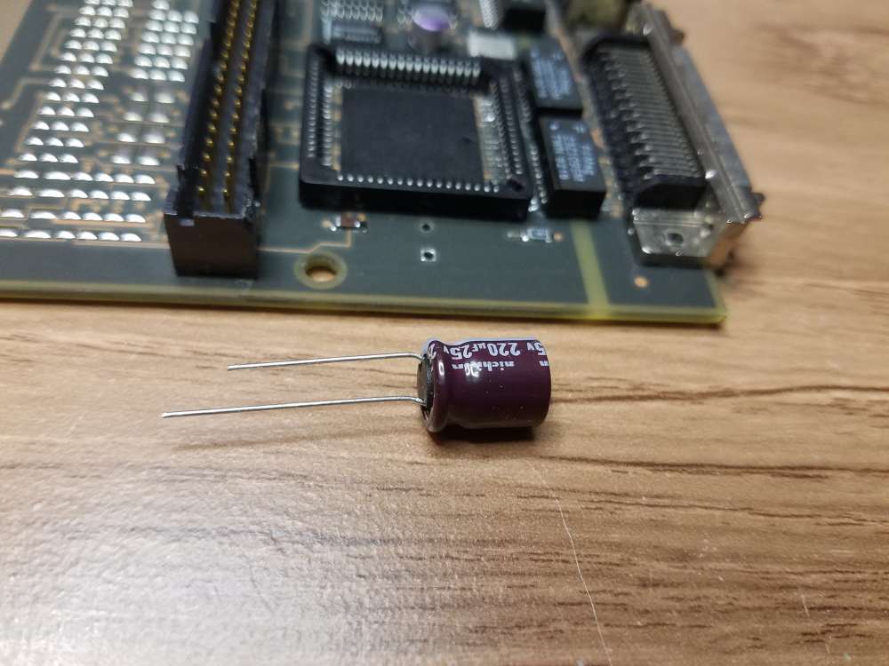
Now it's time to see if the Turbo Color board can be repaired. It has a damaged RAM slot with a missing end, a BNC connector with broken mounting posts, and a 220 µF electrolytic capacitor that was violently ripped off the board. Since one of the caps is literally missing it's a good time for a recap too. I have some caps left over from a recent marathon recapping session (recapathon?), so no need to buy those. I picked up a new BNC connector on eBay and a new 72 pin RAM socket from Mouser.
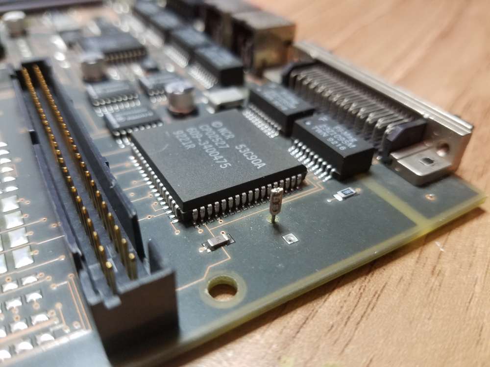
As you can see here, one of the leads was pulled out of the capacitor body and the other lead was pulled through the solder joint. Yikes. The 53C90A SCSI chip has a skid mark as well.
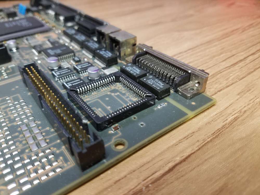
The RAM slot along the edge of the board took a direct hit that knocked the end off. The new one is made by AMP, same as the originals. It has slightly different metal retainer clips and a notch along the front edge. The 72 pin socket is Mouser part #571-5822021-4.
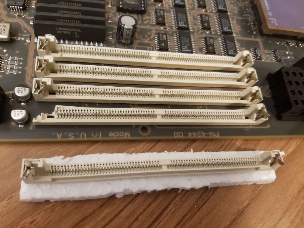
A desoldering iron (https://www.amazon.com/RadioShack-45-Watt-Desoldering-Iron/dp/B007Z7MNEM) was used to remove the old RAM slot, which took a bit of time to complete. The new slot had a third plastic mounting post in the bottom center, unlike the originals, but fortunately the motherboard has holes for the extra post.
Next I used SMD desoldering tweezers to remove the surface mount caps and a standard soldering iron to free the remaining radial lead capacitors. After a little cleanup the new caps were soldered in place.
The last repair to make was the BNC connector. After unsoldering the old connector I decided that it would be nice not to have the protruding connector sticking out the back of the slab, so I'll save the new one for the next owner to add back in if they desire. The search is on for a black plastic plug to fill the hole in the back of the slab case. That's pretty much it for the repair and recap.
There's one more thing...
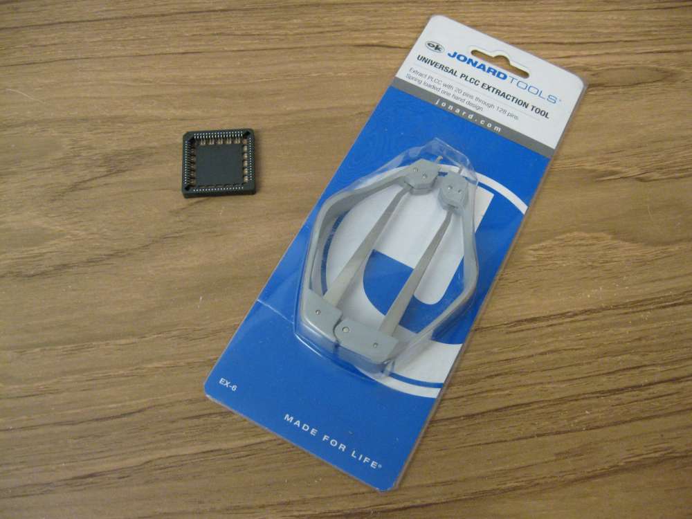
Rob mentioned in another thread (https://www.nextcomputers.org/forums/index.php?topic=4916.msg29160#msg29160) that MrPix had determined that the NCR 53C90A SCSI controller chip that NeXT used could be replaced by a 53CF90A SCSI chip for better performance. All credit goes to MrPix for figuring this out, thank you sir. A big thank you also goes out to Brian for finding some of the chips for sale on ebay (https://www.nextcomputers.org/forums/index.php?topic=4916.msg29162#msg29162). I decided to give it a shot and modify this board for a faster SCSI chip. Since the motherboard was previously damaged and it's unknown if it even works, it makes total sense to sink a lot more time into it. I chose to add a PLCC-68 socket instead of soldering the new SCSI controller chip directly to the board. The socket is Mouser part #517-8468-21B1-RK-TP.
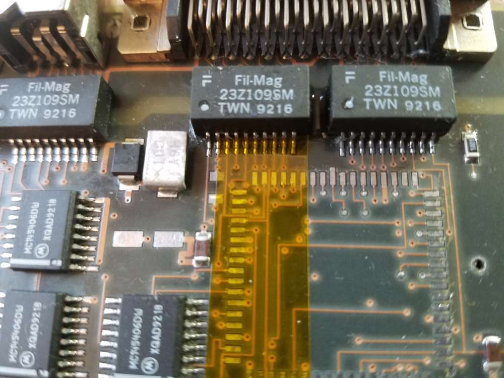
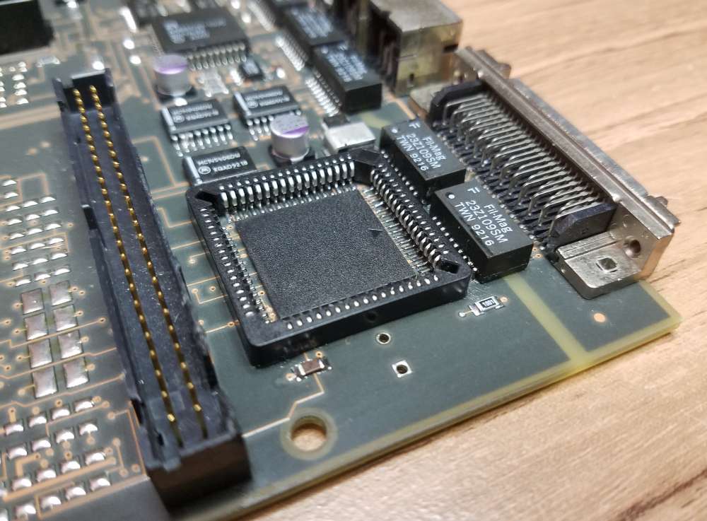
The socket is a tight fit on the Turbo Color motherboard. There's a tiny SMD ceramic cap in the upper left corner of the SCSI chip that's in the way and needs to be moved. The missing radial lead capacitor has a slight interference too and will need to be massaged.
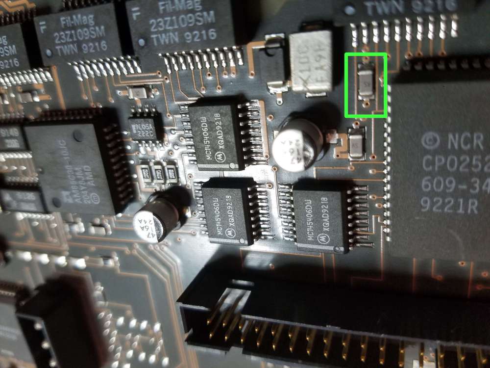
(Notice the original 47µF aluminum capacitor that was damaged in shipping.)
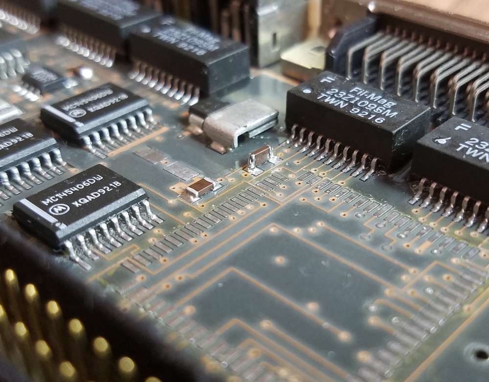
The first task was to remove the tiny SMD cap and clean the solder pads. After that it was time to remove the 53C90A SCSI chip. I made my own PLCC-68 desoldering tips for my tweezer iron out of bent aluminum sheet so that all four sides of the chip could be heated at once.
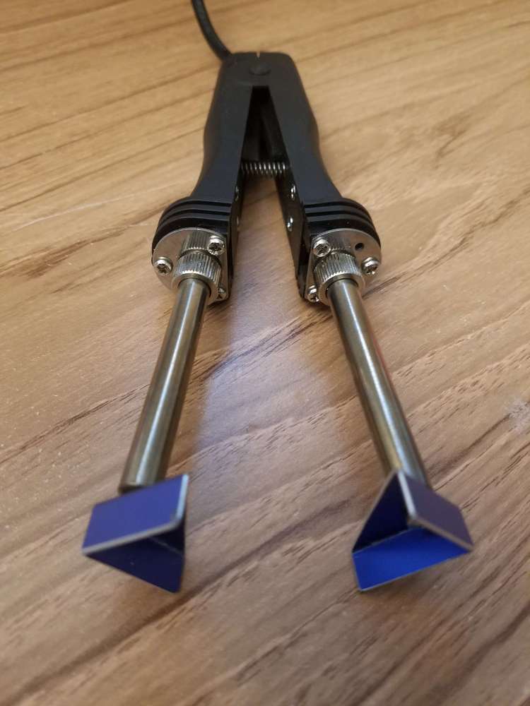
My homemade desoldering tips were not hot enough to unsolder the chip, so an SMD removal kit from ChipQuik (part #SMD1) was ordered, which comes with low melting point solder and sticky flux. I used copper braided solder wick and regular flux to remove as much of the original solder as possible from the 53C90A controller. High temperature tape was placed around the chip, and then low melting point solder was applied all around. After that the homemade desoldering tips worked, although a single soldering iron should work as well. The low melting point solder stays liquid for a long time compared to regular solder.
I decided to flip the tiny SMD cap up on its side and solder it back in place, as the socket just needed a bit more space. You could also relocate the cap as an alternative. After cleaning the solder pads I placed some high temperature polyimide tape over half the width of the pads. This was to prevent solder from covering the full solder pads and touching the underside of the PLCC socket pins. In the future I would cover slightly more than half for better clearance between the socket and the SMD cap. Ideally the cap should be soldered on the very edge of the solder pad for maximum clearance.
Next up was soldering the PLCC-68 socket in place. I went to YouTube University for some guidance. I carefully cut out the center of the socket with an X-ACTO knife for easier access while soldering the socket pins.
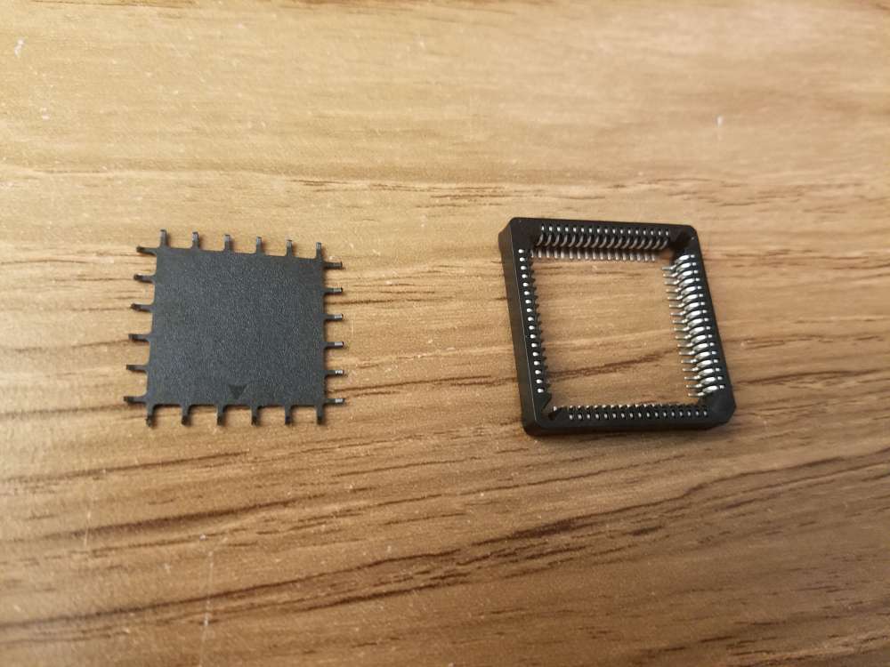
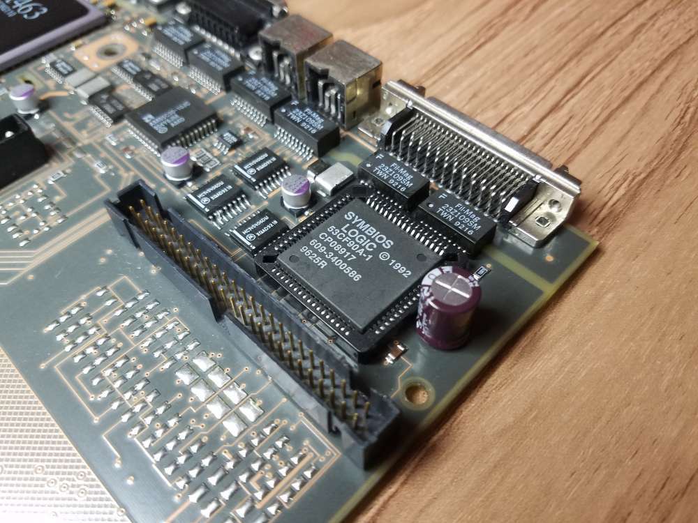
Then the socket was soldered in place. The socket notch should be orientated in the upper left corner so that it's closest to the SMD cap that was removed (see picture below). I used braided copper solder wick to remove excess solder and to touch up the solder joints. After testing continuity between adjacent pins to find any hidden solder bridges I found three tiny loose solder balls. Whew. Although it may not be necessary, I sanded the edges of the socket center that was removed previously and attached it to the board with double-sided tape.
After that it was time to add the last radial lead capacitor. It was necessary to bend the leads close to the base to offset it for additional clearance between the cap and socket. This allowed the cap to sit tight against the PCB.
The new SCSI controller chip installed and ready to go.
Here's the repaired board ready for testing. It has a new battery, v74 ROM, new thermal paste and 128mb of 60ns RAM.
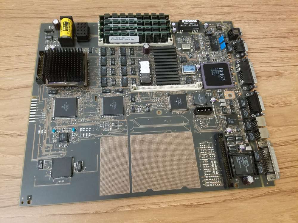
I'm happy to report that it works. The new SCSI controller is identified by NEXTSTEP 3.3 as "SCSI 53C90A Controller". The datasheet for the 53CF90A chip (https://www.nextcomputers.org/NeXTfiles/Docs/Hardware/Datasheets/SCSI_Controller/53C90_Compatible_Chips/NCR_53CF90A_53CF90B_SCSI_IO_Processors_Data_Manual_1993.pdf) says that it's pin and software compatible with the 53C90A.
Here's a few of the 53CF90A features:
• SCSI-2 compatible
• Up to 10 MB/s sustained synchronous SCSI transfer rate
• Up to 7 MB/s sustained asynchronous SCSI transfer rate
• Up to 13.3 MB/s DMA burst transfer rate (FASTCLK enabled)
I'm just guessing here but it will probably require a SCSI2 driver with synchronous support to get the maximum performance out of the chip. That being said, I'll do some testing and benchmarking soon. Although it took me out of my comfort zone, this was a fun repair project.
Title: Re: Turbo Color Slab Motherboard Repair and Recap
Post by: cooltr6 on April 30, 2024, 04:32:20 PM
Post by: cooltr6 on April 30, 2024, 04:32:20 PM
Some beautiful work, my friend...and in a tight space to boot. Doing what needs to be done to keep Black hard ware happy. ❤️
I look forward to seeing the results of the testing and benchmark deets.
I look forward to seeing the results of the testing and benchmark deets.
Title: Re: Turbo Color Slab Motherboard Repair and Recap
Post by: barcher174 on April 30, 2024, 06:03:58 PM
Post by: barcher174 on April 30, 2024, 06:03:58 PM
Fantastic work Nitro! I love making trash useful again!
Title: Re: Turbo Color Slab Motherboard Repair and Recap
Post by: Nitro on April 30, 2024, 08:24:10 PM
Post by: Nitro on April 30, 2024, 08:24:10 PM
Thanks for the encouragement guys! I'm already looking to see if there are any good candidates out there for a SCSI2 driver codebase to port. There may be some good clues in the NetBSD SCSI source code for NeXT. Also, I was looking at the datasheet for the 53CF90A and the maximum SCSI transfer rates are obtained with a 40MHz clock. I guess I better get cracking on the 50MHz overclock project. This battle-scarred wonder may become my daily driver yet.
Title: Re: Turbo Color Slab Motherboard Repair and Recap
Post by: Rob Blessin Black Hole on April 30, 2024, 09:19:10 PM
Post by: Rob Blessin Black Hole on April 30, 2024, 09:19:10 PM
Another Very Top notch NeXT project and successful completion with a lot of excellent pointers on how to repair , rework and upgrade the NeXT Motherboards kudos Nitro!
Title: Re: Turbo Color Slab Motherboard Repair and Recap
Post by: Nitro on May 08, 2024, 04:34:22 PM
Post by: Nitro on May 08, 2024, 04:34:22 PM
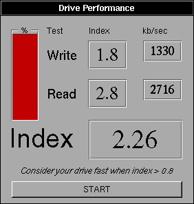
As I suspected, the new 53CF90A SCSI controller runs at the same speed as the original 53C90A with the NeXT SCSI driver. It's going to require an updated SCSI2 driver to take advantage of the new chip's speed. It's easy to swap out the chips now so I'll run more benchmarks if I can come up with an updated driver.
Title: Re: Turbo Color Slab Motherboard Repair and Recap
Post by: sappas on May 09, 2024, 01:51:28 AM
Post by: sappas on May 09, 2024, 01:51:28 AM
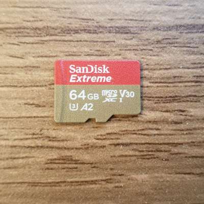
What sd card do you use ?
Title: Re: Turbo Color Slab Motherboard Repair and Recap
Post by: Nitro on May 09, 2024, 10:29:11 PM
Post by: Nitro on May 09, 2024, 10:29:11 PM
Quote from: sappas on May 09, 2024, 01:51:28 AMWhat sd card do you use ?
I'm using this micro SD card (formatted exFAT) with an adapter in an older BlueSCSI V2 2022.12a flashed with the latest firmware.